Table of Contents
Ohm’s Law is a fundamental concept in the field of Physics and serves as the foundation for understanding the behavior of electric circuits. The German physicist Georg Simon Ohm formulated Ohm’s law, which establishes a mathematical correlation between voltage, current, and resistance within an electrical circuit. The formula that links these three quantities is named after him as a tribute to his contribution. Ohm’s law is also included in class 10 Science syllabus and class 12 Physics syllabus. In this article, we will explore Ohm’s law definition, statement, formula, derivation, and limitations, along with a helpful diagram and examples.
Ohm’s Law Definition
Ohm’s Law states that the current flowing through a conductor is directly proportional to the voltage applied across it, while inversely proportional to its resistance. In simpler terms, it relates how voltage, current, and resistance are interconnected within an electrical circuit.
V ∝ I
or, V = I × R
Ohm’s Law Statement
The statement of Ohm’s Law can be summarized as follows: “The current passing through a conductor is directly proportional to the voltage across it and inversely proportional to its resistance, provided the temperature remains constant.”
In simpler words, Ohm’s Law states that the voltage across a resistor is directly proportional to the current flowing through it and inversely proportional to the resistance of the resistor. It is often used to calculate one of these parameters (V, I, or R) when the other two are known in an electrical circuit.
Ohm’s Law Formula
Ohm’s law formula helps to show the calculations that are required to solve for voltage, current, and resistance. Mathematically, Ohm’s Law is expressed using the following formula:
V = I × R
Where:
- V represents the voltage (in volts V)
- I denotes the current (in amperes A)
- R signifies the resistance (in ohms Ω)
Ohm’s Law Explanation
G.S. Ohm made a foundational discovery about electrical currents in 1828, before the physical mechanism behind this phenomenon was identified. Let us suppose, a conductor through which a current I is flowing and let V be the potential difference between the ends of the conductor.
Then Ohm’s law states that,
V ∝ I
or, V = I × R
Where:
R is the proportionality constant (called Resistance)
The SI unit of resistance is ohm and is denoted by the symbol Ω.
So, According to Ohm’s law, ” The voltage of the conductor is directly proportional to the current flowing through that conductor.
| Three Quantities Related to Ohm’s Law | |||
| Quantity | Symbol | Unit | Unit Symbol |
| Current | I | Ampere | A |
| Voltage | E or V | Volt | V |
| Resistance | R | Ohm | Ω |
Ohm’s Law Diagram
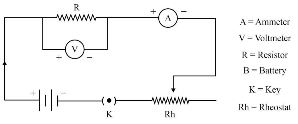
In 1827, German physicist Georg Simon Ohm (1787–1854) found out the relationship between the current I, flowing in a metallic wire and the potential difference across its terminals. The potential difference, V, across the ends of a given metallic wire in an electric circuit is directly proportional to the current flowing through it. The electric circuit diagram obeys Ohm’s law is given below.

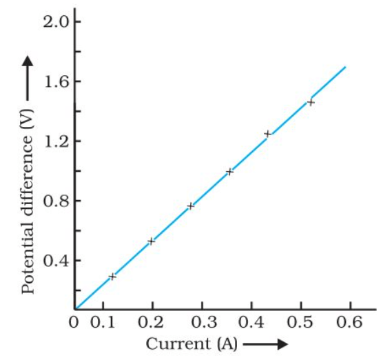
The V–I graph for a nichrome wire is given below. A straight-line plot shows that as the current through a wire increases, the potential difference across the wire increases linearly – this is Ohm’s law.

Ohm’s Law Relationship Between Voltage, Resistance, and Current
In the early 19th century, German physicist Ohm discovered that the current passing through a conductor is directly proportional to the voltage across the conductor. His discovery came to be known as Ohm’s Law, which describes the relationship between voltage (V), current (I) and resistance (R):
V = I R, ( For calculating Voltage)
I = V/R, (For calculating Current)
R= V/I (For calculating Resistance)
Derivation of Ohm’s Law
To derive Ohm’s Law, we can use the concept of electrical resistance. Resistance is a measure of how much a material opposes the flow of electric current. It depends on factors such as the material’s composition, dimensions, and temperature.
Consider a conductor with a uniform resistance R, connected to a voltage source V. According to Ohm’s Law, the current I flowing through the conductor can be determined by dividing the voltage by the resistance:
I = V / R
This equation demonstrates the relationship between voltage, current, and resistance, and is the derived form of Ohm’s Law.
Experimental Verification of Ohm’s Law
Suppose A conductor of resistance (R) ohms is connected in series with an ammeter (A), rheostat (variable resistance) and a battery (B)B through key K(K). A voltmeter (V) is connected across the ends of the resistance which helps to measure the potential difference across it.
Then a key (K) is pressed and readings of the voltmeter and ammeter are recorded. After reverting, the key (K) the setting of the rheostat is changed, Key(K) is again pressed and voltmeter and ammeter readings are recorded. Thus, for various settings of a rheostat, the reading of the voltmeter and ammeter are noted. From the monitoring, it can be seen that the ratio of voltmeter reading and ammeter reading always remains the same every time i.e.
V1/I1 = V2/I1 = V3/I3 = V4/I4 = ……… = Constant = R( Resistance of the Conductor)
Limitations of Ohm’s Law
While Ohm’s Law is a valuable tool for analyzing many electrical circuits, it does have certain limitations. Some of the limitations of Ohm’s law are-
- It assumes that the conductor under consideration has a constant resistance, regardless of the applied voltage or current. However, in reality, some materials, such as semiconductors and nonlinear resistors, do not strictly adhere to Ohm’s Law.
- Ohm’s Law is not applicable to certain electrical components, such as capacitors and inductors, which exhibit different characteristics.
- Ohm’s law is not applicable to Unilateral electrical elements such as diodes and transistors as the following of current is only in one direction only.
- Ohm’s law is applicable only to Ohmic Conductors such as iron and copper not to non-ohmic conductors.
Applications for Ohm’s Law
It is a fundamental principle in electrical engineering and has numerous applications across various industries. Here are some common applications of Ohm’s Law:
- In fuses
- To know the power consumption.
- To control the speed of fans.
- For deciding the size of resistors.
- To determine the voltage, resistance, or current of an electric circuit.
Ohm’s Law Solved Examples
Example 1: If the resistance of an electric coil is 60 Ω and a current of 3.2 A flows through the resistance. Find the voltage between two points.
Solution: According to the question, Resistance = 60 Ω
Current = 3.2 A
So in order to calculate the voltage we can use the formula, V = IR
V = I × R
V = 3.2 A × 60 Ω = 192 V
So the Voltage between the two points in the electric coil is 192 V.
Example 2: An EMF source of 10.0 V is connected to a purely resistive electrical appliance (a light bulb). An electric current of 5.0 A flows through the bulb. Consider the conducting wires to be resistance-free. Calculate the resistance of the appliance.
Solution: According to the question, the Voltage of the source = 10V
Current = 5.0 A
So in order to calculate the resistance we can use the formula, R= V/I
R = V/I
R = 10 V/5 A
R= 2Ω
Example3: If the resistance of an electric iron is 150 Ω and the current flowing is 5.2 A through the resistance. Find the voltage between two points.
Solution: According to the question, Resistance is 150 Ω,
The current flowing is 5.2 A
So in order to calculate the voltage we can use the formula, V = IR
V = 5.2 x 150
V= 780Ω
Example 4: Find the current I through a resistor of resistance R = 9Ω if the voltage across the resistor is 18 V.
Solution: According to the question, Resistance is = 9Ω
and the Voltage across the resistor is 18V
So in order to calculate the voltage we can use the formula, I = V/R
I = 18/9
I = 2A
Example5: In the circuit below resistors R1 and R2 are in series and have resistances of 10Ω and 15 Ω, respectively. The voltage across resistor R1 is 5 V. Calculate the current passing through resistor R2 and the voltage across resistor R2.
Solution: According to the question, R1 = 10Ω
R2 = 15 Ω
Voltage across R1 = 5V
So let us first calculate the current(I) across the R1.
So, I = V/R
I = 5/10
I1 = 0.5 A
We got the current for R1, that is, 0.5 A
So, when two resistors are connected in series then the current flowing through the R1 will be the same across R2.
I1 = I2 = 0.5A
Let us calculate the resistance across the resistor
V2 = I2R2
V2 = 0.5 X 15
V2= 7.5 volt
Ohm’s Law is a fundamental principle in physics and electrical engineering, offering a straightforward relationship between voltage, current, and resistance. Ohm’s law is one of the most important topics for Class 10 and Class 12 students. So every science student in Classes 10 and 12 has read this article properly. While Ohm’s Law has its limitations, it remains an indispensable tool for basic circuit analysis and serves as a starting point for further exploration into the vast world of electrical engineering.
| Related Links | |
| Newton’s Laws of Motion | Newton’s First Law |
| Kepler’s law | |


 CBSE Class 12 Physics Viva Questions wit...
 All 8 Planets Names in English
 Difference Between Rotation and Revoluti...


